
Finally, the acrylic and aluminium have arrived. Of course, now that the software woes are behind me, this means only one thing: time to start building!
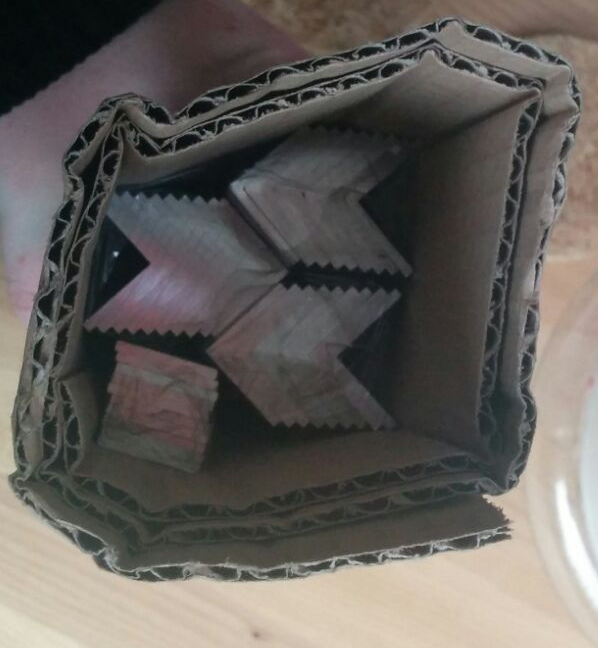
Because I asked the acrylic shop to send me all the “rest” material (the stuff that was cut out) as well, it all came stuck in large panels with sticky tape. I had 30 minutes of fun carefully prying all the different shapes out. The aluminium came is an open cardboard roll.
|
|
|
|
|
|
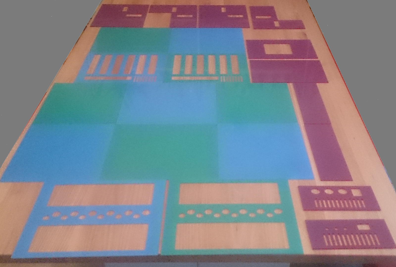
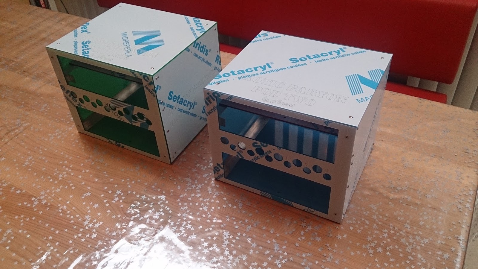
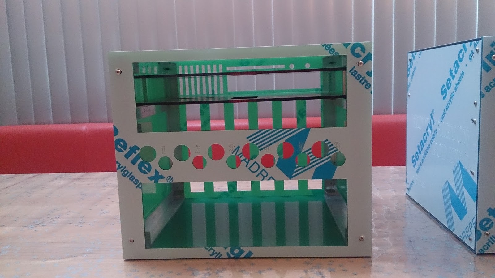
The acrylic has a protective plastic sheet on both sides, one side transparent blue, the other side white with publicity markings. This is why the arculic is not transparent at the moment. I removed the protection from a couple of small “rest” pieces, and it looks very nice.
I do see a difference in thickness between the colors: the blue and green are the same thickness, but the red is about a mm thicker. This will cause some problems with my measurements, but I hope it will not be too visible…
The aluminium is nice and shiny. I did fear that the edges would be very sharp, but they seem to have been sanded so no problem there. There is a problem with the brackets that will hold the fan assemblies in the housing: two thirds of those are not 2 mm, but only 1 mm thick. These will be mounted on the inside, so visually there is no problem, but these pieces feel very flimsy… I hope they will be able to carry the weight of the fans…
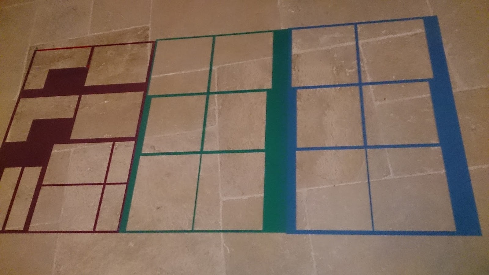
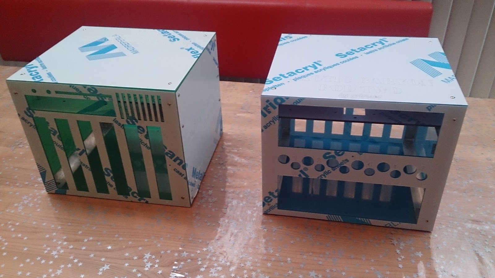
The Green and Blue compute housing
 |
 |
 |
 |
 |
 |
I have not yet removed the protective plastic sheets yet because I will need to disassemble the boxes when I install the hardware.
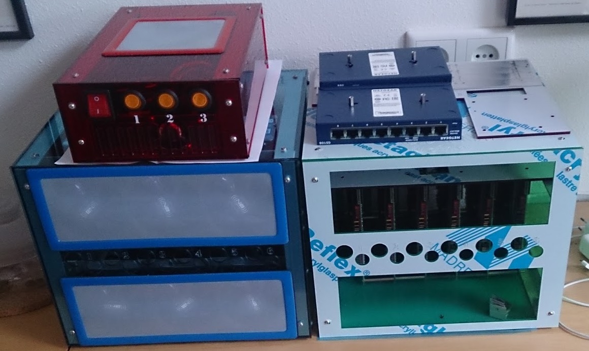
The Red Power Pod completed
|
|
|
|
|
|
|
|
|
|
|
|
|
|
|
|
|
|
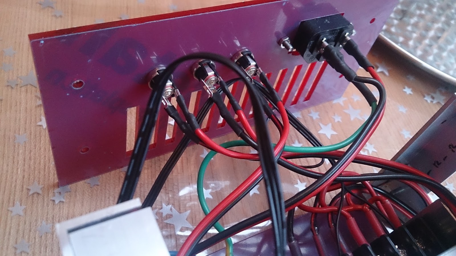
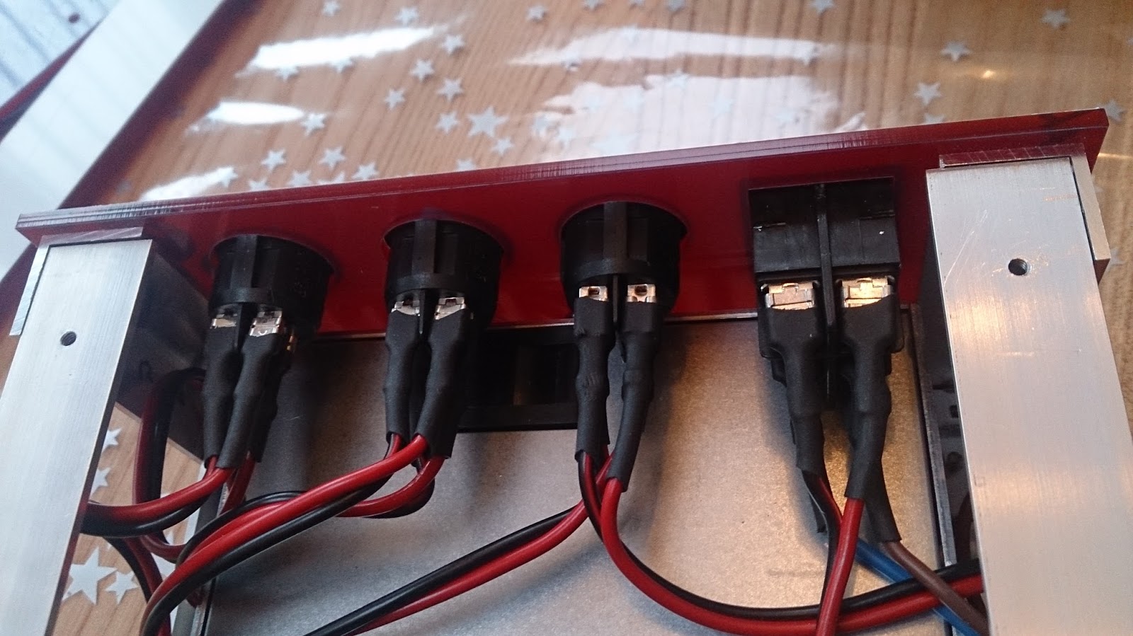
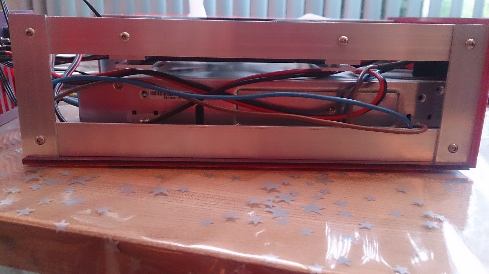
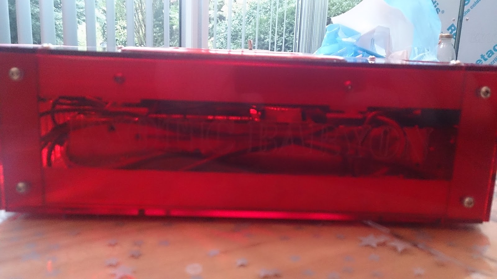
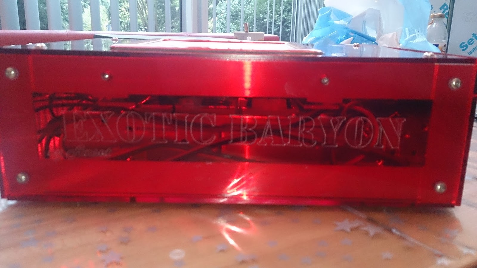
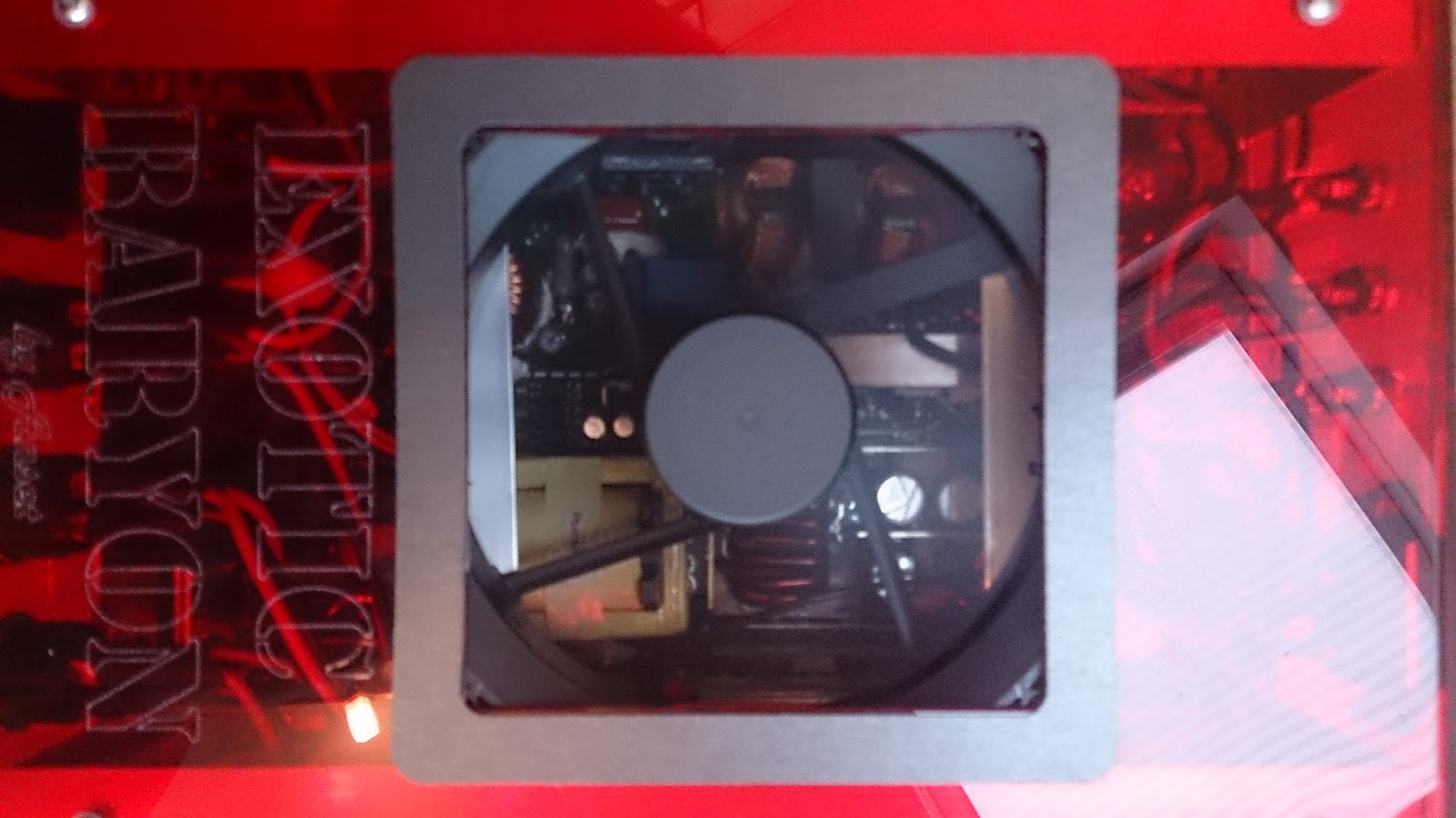
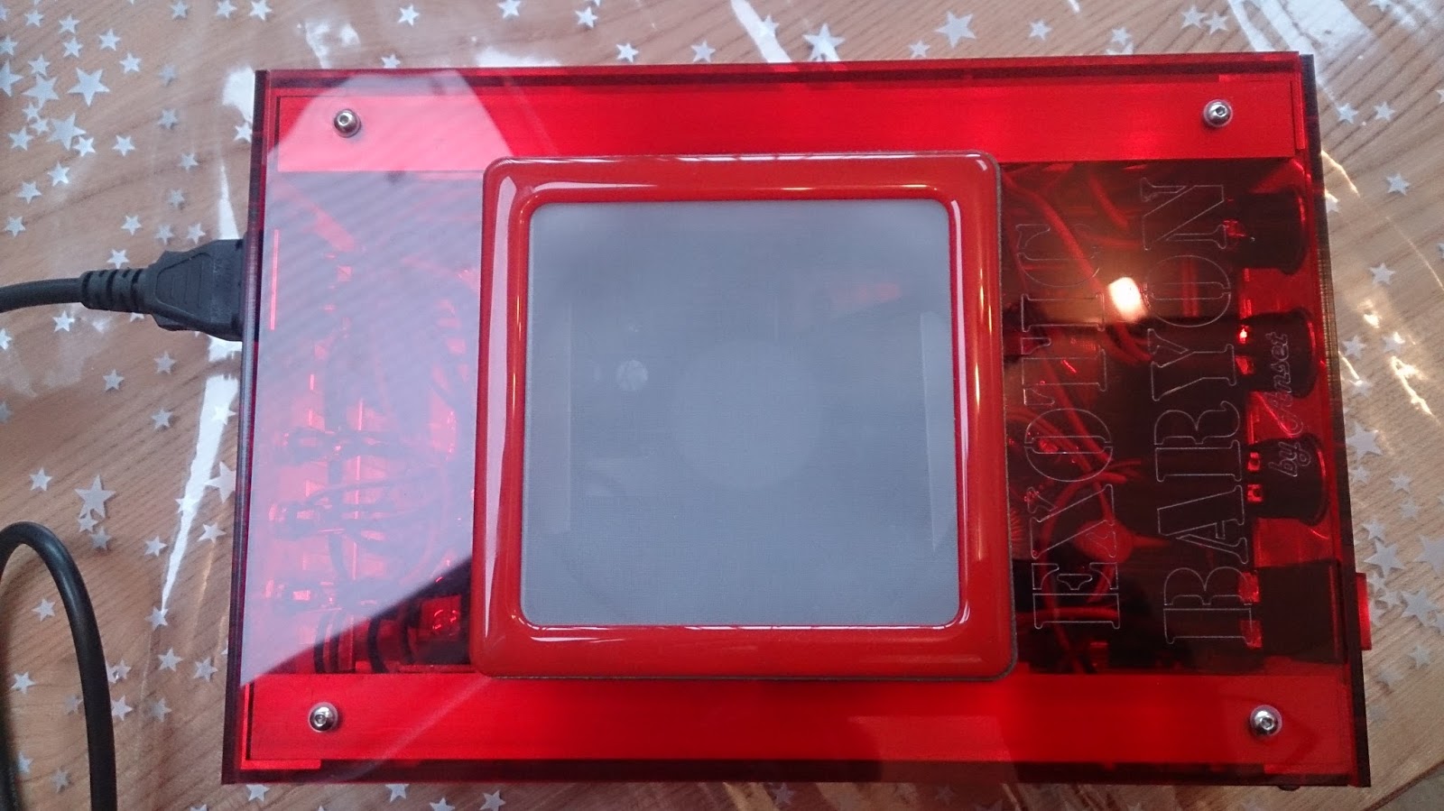

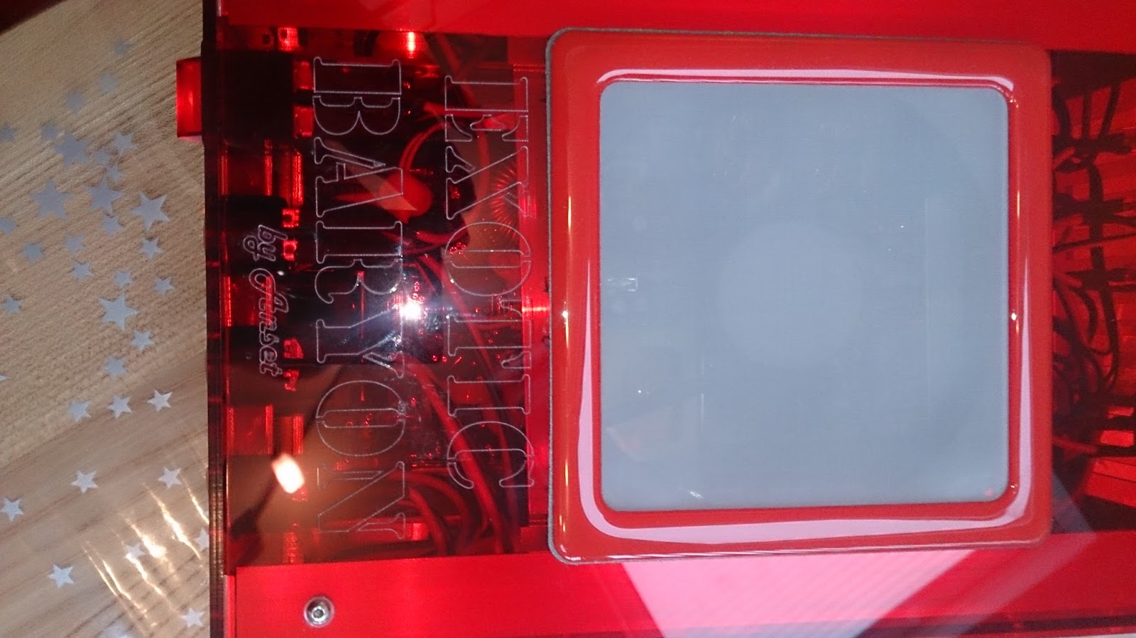
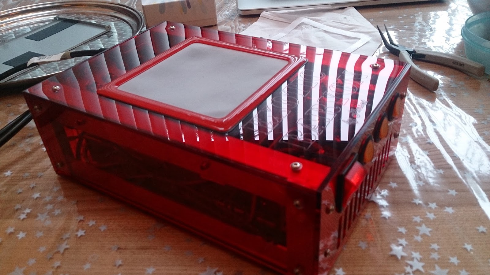
And some “beauty shots” of the power pod with the protective plastic removed and the fan filter installed.
The red acrylic looks very nice, allowing to see the inside of the pod. (Showing off the nicely sleeved cables.) The etching I put on the acrylic is barely visible unless you have to right lighting. But I knew this in advance and I like the fact that the writing is subtle.
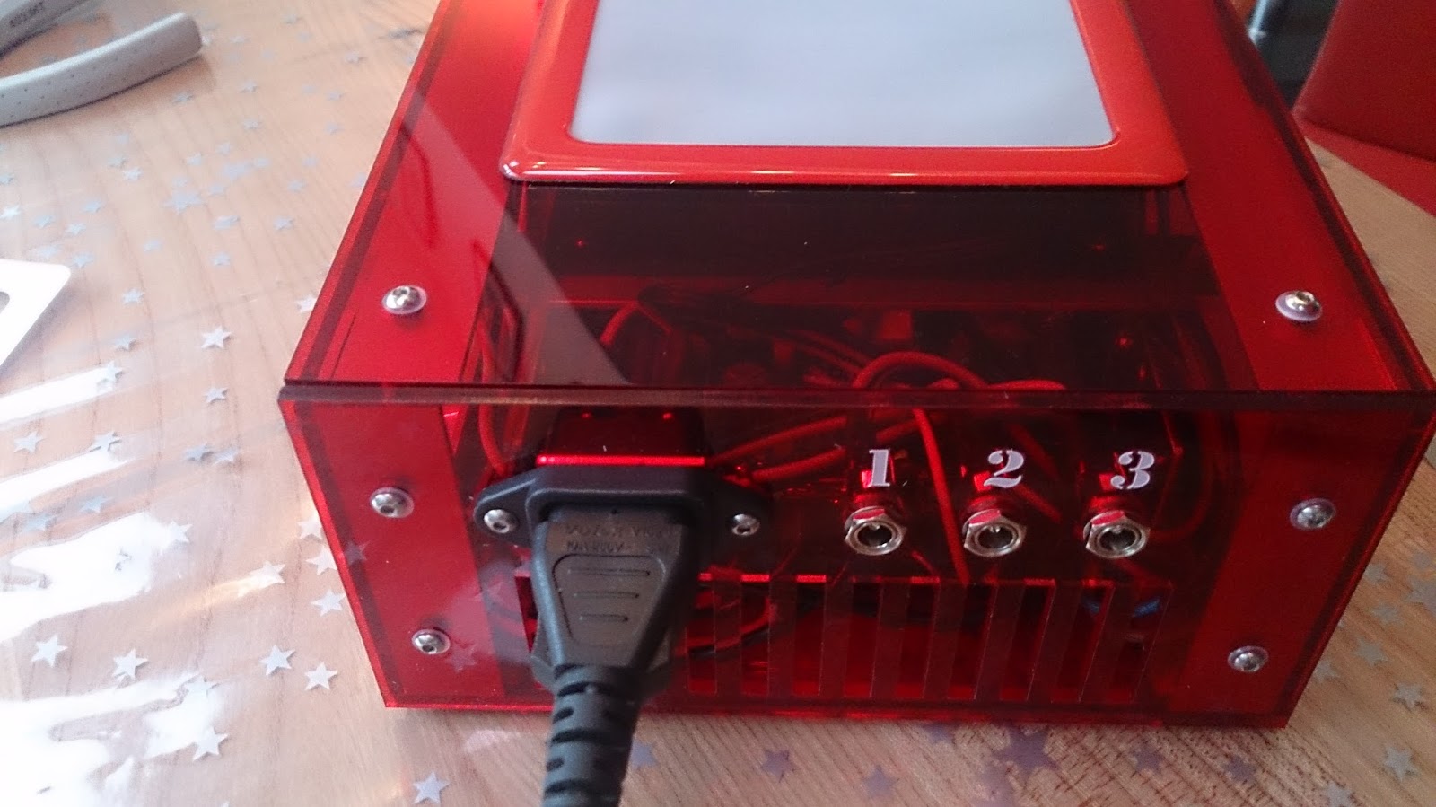
Testing the power pod and all the switches was successful. The main red switch applies power to the power supply and that makes the fan spin. The three 12V outputs from the power supply are not available until the yellow switches are flipped over. This will allow me to power each compute pod separately. Since the power supply has three 12V outputs, I built three separate output circuits, even though I only need two for the two compute pods I am building.
Sadly, like the Red switch, the LEDs in the yellow switches only work when they get 220V, so they do not light up.
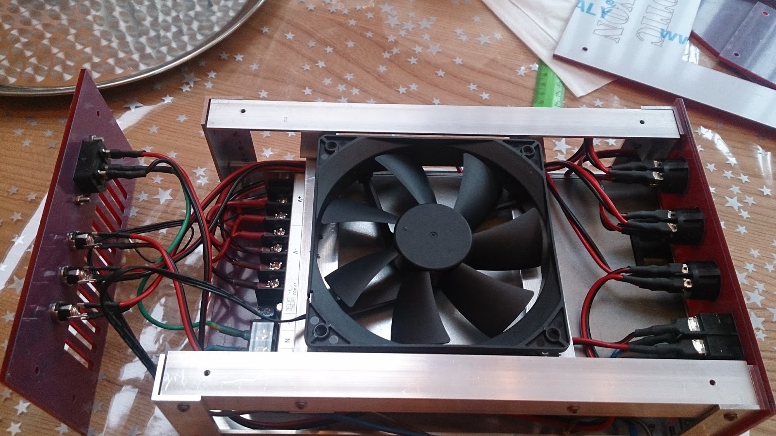
The power supply has a 35 mm turbine fan and that one is very loud so the goal for the 120 mm top fan is to make sure it never needs to spin up. Installing the top fan to turn at the highest rpm seems to do the trick for now, but without any load, that is not that surprising. I have to wait until the compute pods are done before I know if I will need to arrange further cooling.
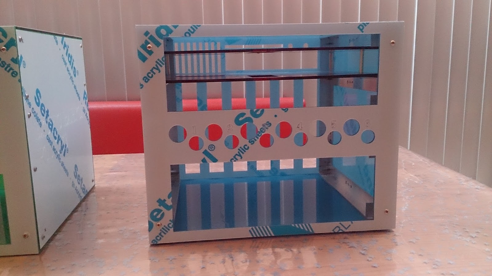
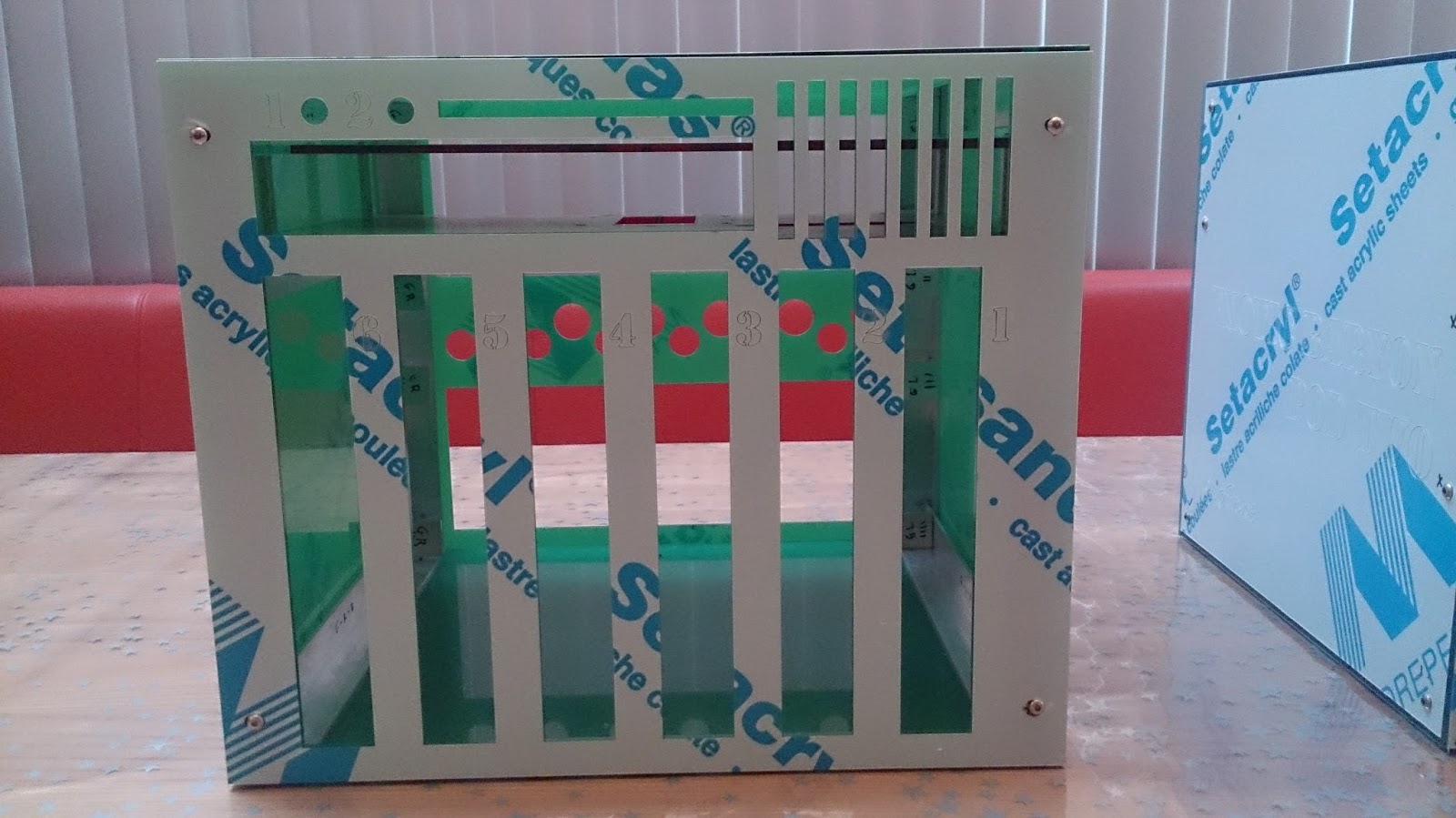
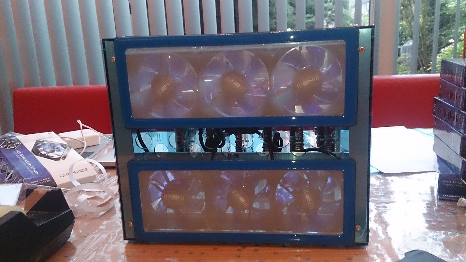
Blue and Green Pod motherboard and fan install
 |
 |
 |
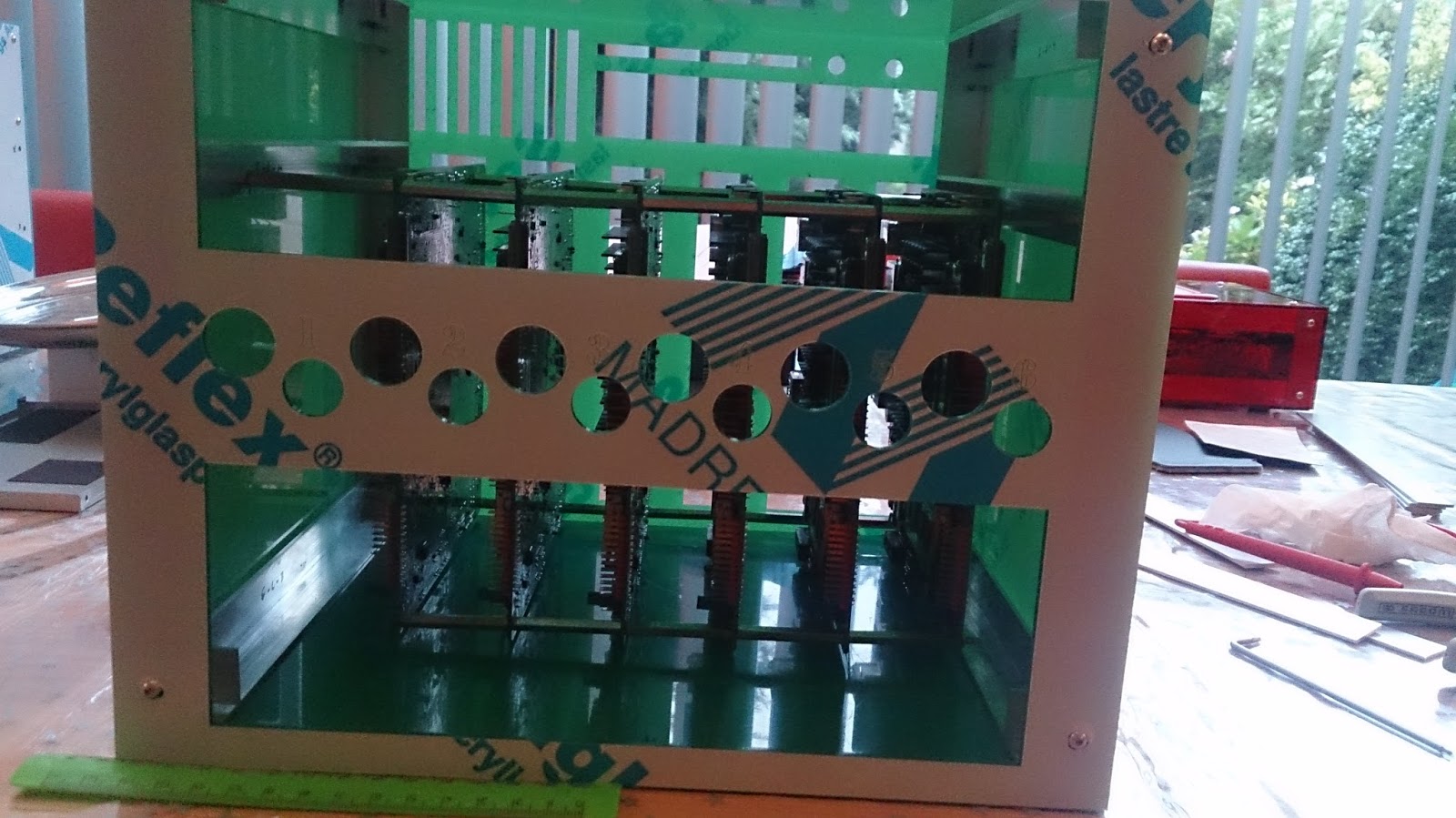
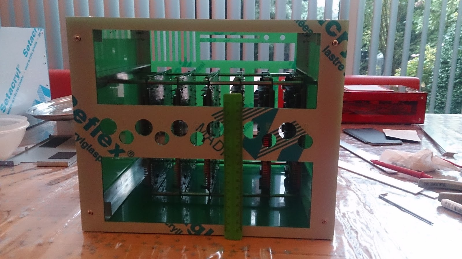
Front and rear views of the motherboard assemblies installed in the housing. I am very happy with the alignment of the motherboard IO ports. (The measuring stick shows centimeters.)
 |
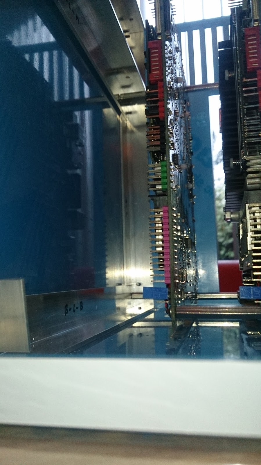 |
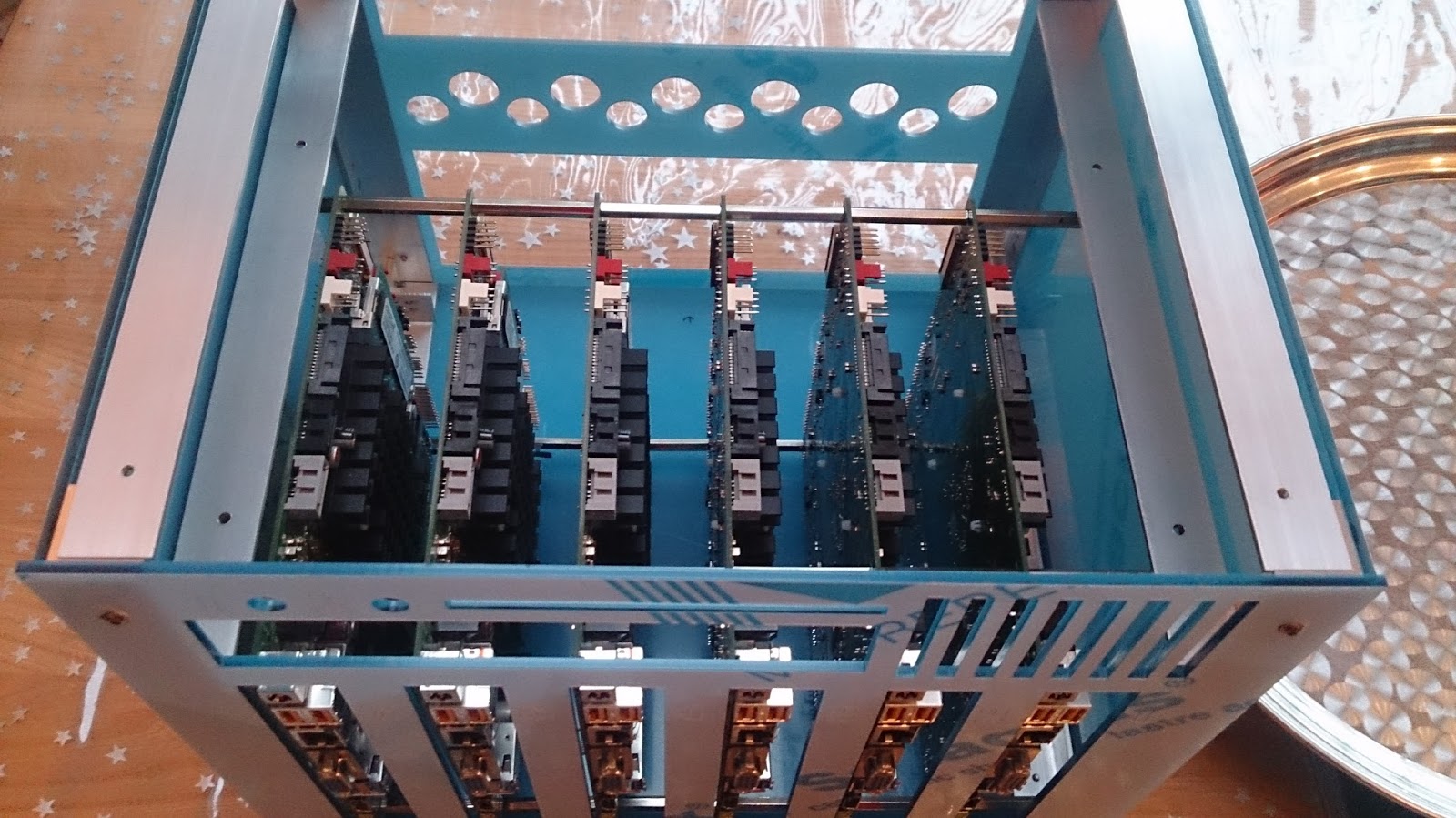
A top view and detail view of the fixation of the motherboard assembly. The housing becomes very rigid with the motherboards installed, which is perfect!
Next step, mounting the fan assemblies:
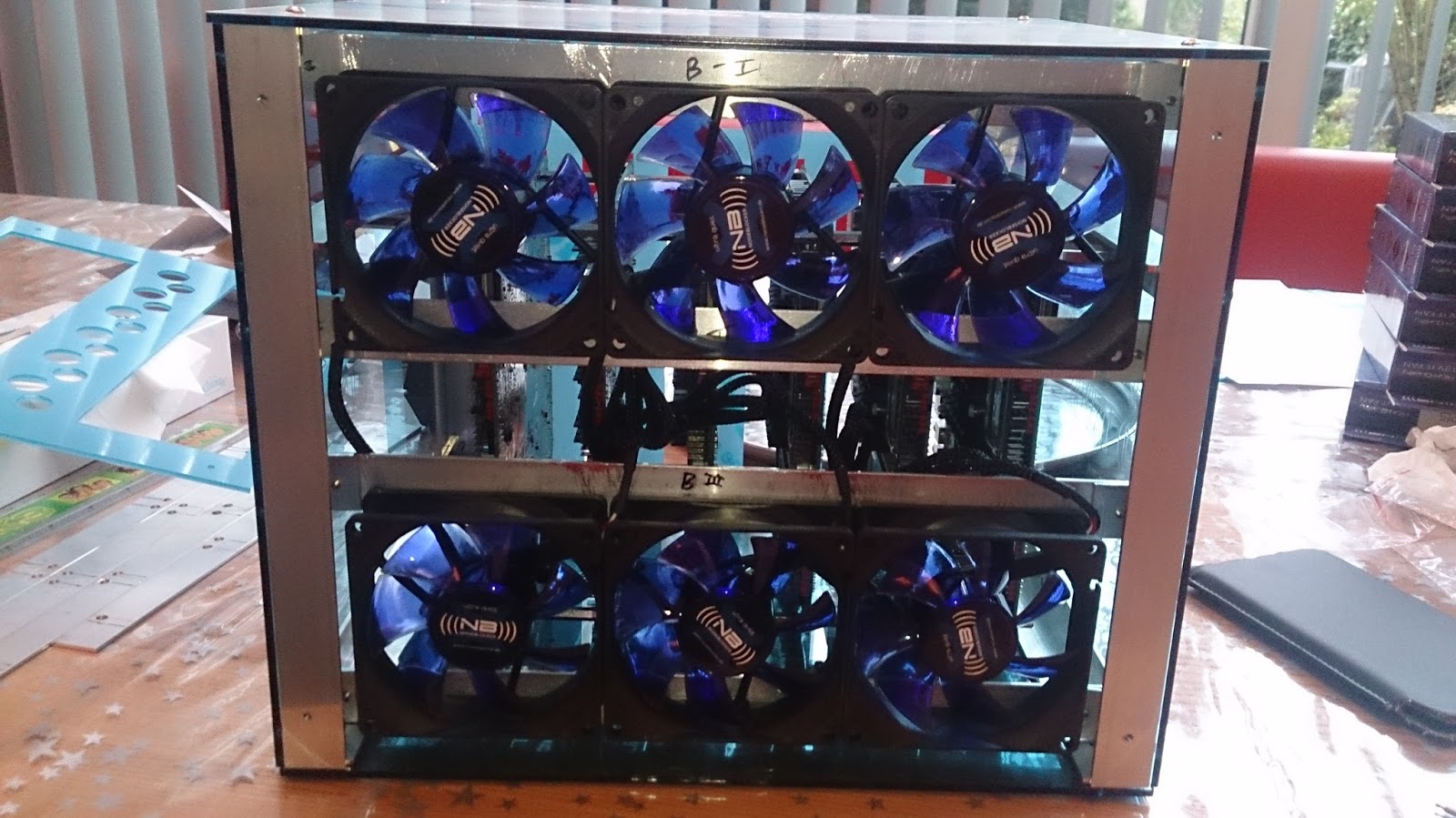 |
||
 |
Since I will not need to disassemble the cases one the fans are installed, I removed the protective plastic sheets. The acrylic now becomes transparent, showing off the innards of the case, as it is supposed to do. All in all, it’s looking very nice indeed!
Current Status of the cluster build
After four days of working on the cluster, this is the current result:

Power Pod: Fully functional
Blue Pod: Case assembled and fans installed
Green Pod: Case assembled
I have purchased a few bits and bobs, but not enough to warrant an update of the cost table. I will definitely put a cost table up when I am finished with the build.
Next time, the green pod will of course also get it’s fans and both pods will receive their disk+switch trays. Hopefully I will also be able to start with the cabling of the compute pods.